
9 Volt Battery Chargers
Constant Current Battery Charger from 2 LED's and a NPN Transistor

Dual Channel Board
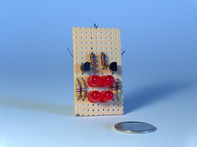
 Front |
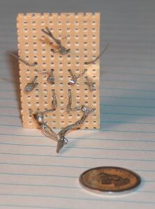 Back |
Diode Voltage Drop
Within limits, the supply voltage can vary but there is a constant voltage drop across the led, a diode, or a transistor.Diodes and transistors drop about 0.6V. LED's vary. Very accurate diodes built for this purpose are called Zener diodes and come in a variety of voltages.
How It Works
The blue side provides a constant voltage.The black side converts a constant voltage to a constant current.
The 1K resistor and 2 LED's create a constant voltage of 3.19V.
The 3.19V flows into the base of the transistor, get reduced by one diode drop (about 0.6V) and comes out the emitter at 2.66V.
The 2.66V emitter voltage and 235 ohm resistance determine the current output of this circuit.
The current output can be calculated by Ohms Law.
I = E / R = 2.66 / 235 = 0.011
Blue Side - Constant Voltage Source
There are quite a few different circuits you can build to provide a constant voltage. You can use Zener diodes, 3 pin regulators, LED's, diodes or even a transistor.I used two LED's stacked in series to give a constant voltage of 3.19V. This changes slightly as the circuit warms up.
Black Side - Emitter Follower
The transistor tries very hard to make to makeEmitterVoltage = BaseVoltage - 0.6v
But to do that, 11 mA must flow through the 2 paralleled 470 ohm resistors
I = E / R = 2.66 / 235 = 0.011
The transistor does not care if the current flows through the base, or through the collector.
Nearly all the current needed will be pulled through the collector and not the base. The ratio of collector current to base current is equal to the gain of the transistor. The 2N2222 I used has a gain of 200, so very little current flows through the base.
Within limits, the transistor will pull 11 mA collector current no matter what load is hooked up to it. The load can be a resistor, a led, a battery, or even a short circuit.
Results
| A | B | C | D | E | |
| mA | 10.8 | 10.8 | .1 | 10.8 | 10.8 |
Comments
When the power gets disconnected, the battery discharges. There should be a diode between the transistor and the battery to prevent this.I built a 2 channel charger to charge 2 batteries at once. You can hook both channels in parallel to one battery for fast charging.
This circuit can be used as a constant current source for LED's.
The voltages and current on the schematic are actual measurements, not calculated or simulated values. That's why they don't quite add up.
The transistor can be any NPN. I used a 2N2222. The resistors are 1/4 Watt.
I recommend building the blue part first with the LED's or diodes you have on hand. The 1K resistor should work with power supplies from 12 - 20 Volts. Then measure the voltage on the top of your diode string. Subtract .6V and you have the voltage to plug into Ohm's Law to calculate the value of the base resistor.
E = 3.19V - .6V
I = 0.011
R = E / I
R = 2.56 / 0.11
R = 232 Ohms
References
-
4QD-TECH
Current sources and mirrors
Ā http://www.4qdtec.com/csm.html

|

|
Charge Rate
Wall Warts
Simple 1 Resistor Battery Charger
Constant Current Battery Charger from 2 LED's and a NPN Transistor
9V Battery Charger from 2 NPN Transistors
Adjustable Charge Rate Battery Charger from Op Amp
0 - 160 mA Adjustable Charge Rate Battery Charger
Test Results
741C Cheat Sheet
sparksandflames.com
Sparks and Flames
Line2:
Fax:
Copyright © 2020