9 Volt Battery Chargers
Adjustable Charge Rate Battery Charger from Op Amp

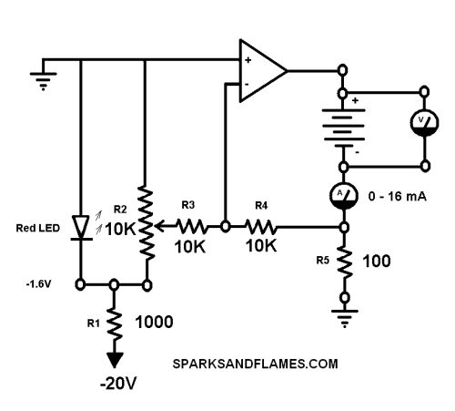
This circuit uses a potentiometer and an op-amp to make a adjustable constant current source.
The voltage drop across R5 is compared against an adustable voltage from R2. The op-amp is wired in an inverting configuration with a gain of 1.
The op amp I used was a 741C from Radio Shack. The 741C is rated for 20 mA. I got 20mA from the op-amp for a full 10 hours. I got 25mA for a few minutes, and then the op-amp shut down. The op-amp worked fine again after it cooled down. See version 5 on using a transistor for more current.

Use star grounding. This means run all grounds to a single physical point. This made a big difference in stability between the first and second time I breadboarded the circuit.
Touching the shaft of the rheostat causes a slight change in output current.
This circuit can withstand a short circuit.
The Negative battery terminal is not at ground!
The op-amp connections to the plus and minus supplies are not shown.
R5 is also know as the sense resistor. The voltage across R5 is directly proportional to the charging current.
The red led produces a reference voltage of 1.6V.
Vin = 1.6
Gain = 1
Vout = Vin * Gain = 1.6 * 1 = 1.6
Iout = E / R =  Vout / R5 = 1.6 / 100 = 0.016 A = 16 mA
Make R5 smaller to get more current. I = 1.6 / R5
This circuit works well for dimming leds. (a.k.a. Led Dimmer.)
References
-
University of Denver
Operational Amplifiers -- DC
www.du.edu/~etuttle/electron/elect3.htm -
Shavano Music
Introduction to Op-Amps - Part 1
www.colomar.com/Shavano/intro_opamp.html -
Shavano Music
Introduction to Op-Amps - Part 2
www.colomar.com/Shavano/intro_opamp2.html -
Michael Gellis
A Constant Current Source for a Grounded Load using a Single Op-Amp
members.tripod.com/michaelgellis/howland.html -
Elliott Sound Products
Audio Design with Opamps
sound.westhost.com/dwopa.htm -
eCircuit Center
Opamp Current Source
www.ecircuitcenter.com/Circuits/curr_src1/curr_src1.htm -
Hans Camezind
Designing Analog Chips
www.designinganalogchips.com/_count/designinganalogchips.pdf

|

|
Charge Rate
Wall Warts
Simple 1 Resistor Battery Charger
Constant Current Battery Charger from 2 LED's and a NPN Transistor
9V Battery Charger from 2 NPN Transistors
Adjustable Charge Rate Battery Charger from Op Amp
0 - 160 mA Adjustable Charge Rate Battery Charger
Test Results
741C Cheat Sheet
sparksandflames.com
Sparks and Flames
Line2:
Fax:
Copyright © 2020

